
The Airborne eXpendable Buoy Processing System (AXBPS) Data Acquisition System is designed to receive pulse code modulated (PCM) audio data containing an AXBT, AXCTD, or AXCP profile signal and produce viable temperature-depth, temperature- and salinity-depth, or temperature- and current-depth profiles (respectively) from that data. AXBPS is compatible with WiNRADIO software-defined radio receivers, which demodulate a VHF signal transmitted from an air-launched probe and export the resulting PCM data to AXBPS for processing. Additionally, previously recorded WAV files can be imported into AXBPS to decode the transmitted profile(s). AXBPS integrates the signal processing capabilities of the MK-21 or similar hardware and audio recorders as software-defined functions, reducing the equipment necessary to launch and process data from AXBTs and AXCTDs. AXBPS was also developed with the intent of simplifying the integration of additional radio receiver types in the future.
Layout
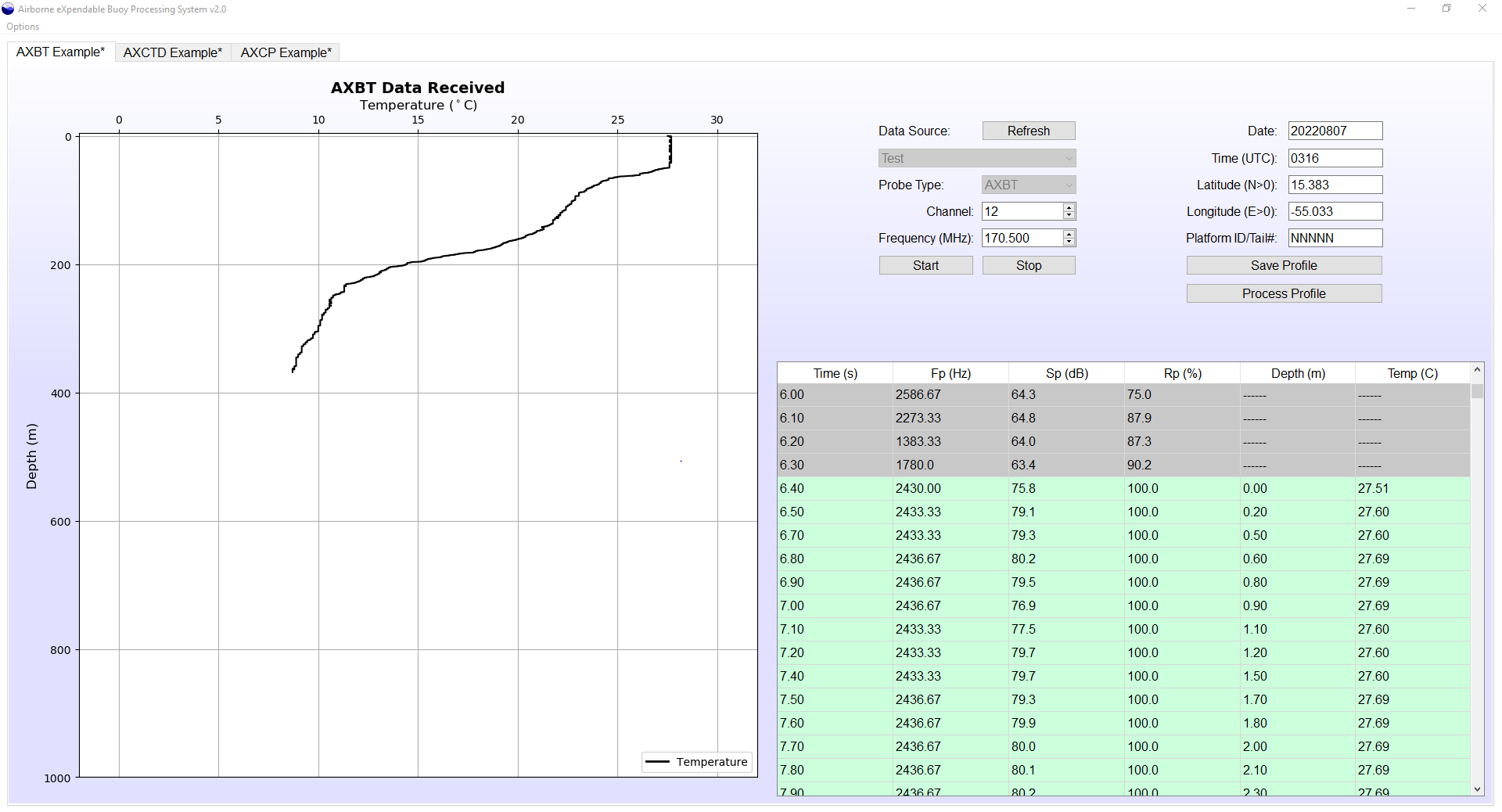
An AXBPS Data Acquisition System graphical user interface (GUI) tab is opened by default when starting AXBPS. Additional Data Acquisition System tabs can be opened by either selection "Options > New Processor Tab" or using the keybinding ctrl+N. The Data Acquisition System window is divided into three sections:- Raw, realtime data-versus-depth profile plot (left)
- Tabular profile and signal information (lower right)
- Probe type, data source, VHF, and profile metadata configurations (upper right)
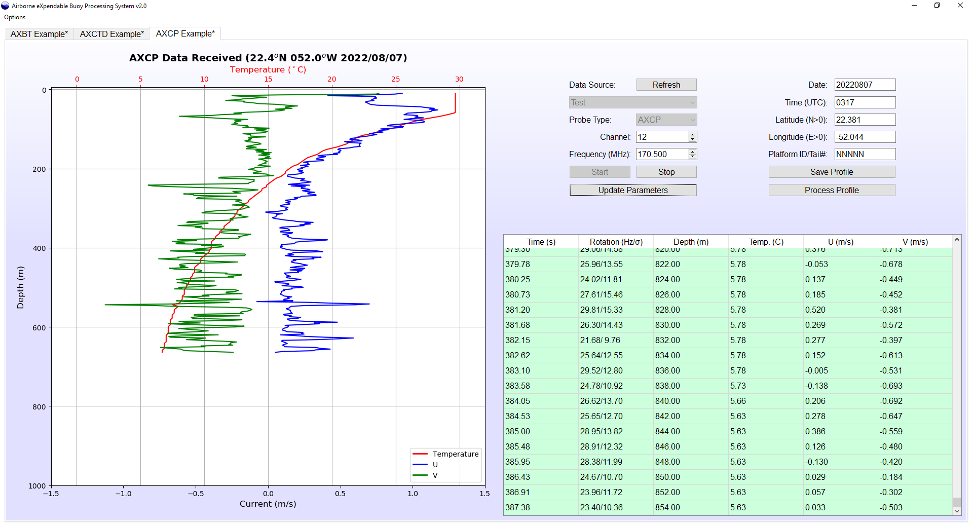
The upper-right corner of the GUI provides options for the user to control the Data Acquisition System. There are two columns with user inputs. At the top of the left column, a dropdown menu allows the user to select the data source from which AXBT data is being processed. The datasource selection dropdown menu automatically has two default options: "Test", which processes a test signal (from a raw audio file distributed with AXBPS), or "Audio", which prompts the user to select a raw WAV file to be reprocessed. Additionally, on Windows systems with the WiNRADIO drivers installed, any connected WiNRADIO receivers will be listed by serial number in order to process data in realtime. Because each receiver can only demodulate one channel at a time, AXBPS prevents the user (with a warning message) from selecting the serial number for a WiNRADIO that is actively receiving in a different tab.
The "Probe Type" dropdown menu allows the user to switch between AXBT, AXCTD, and AXCP processing modes. In addition to switching the signal processing method to be used, this selection reconfigures the table and plot to display AXBT (temperature only), AXCTD (temperature and salinity), or AXCP (temperature and current) information.
If a connected WiNRADIO receiver is selected, the two spinboxes immediately below the datasource selection menu (labelled "VHF Channel" and "VHF Frequency") allow the user to select the VHF frequency that the receiver demodulates, either directly by frequencies or by selecting the corresponding sonobuoy VHF channel (selecting a new frequency will update the selected channel, and vice versa). The VHF channel and frequency being demodulated can be changed while a receiver is actively processing data.
Buttons for the user to start and stop data acquisition are located at the bottom of the left column. Data acquisition can be restarted after being stopped (except when reprocessing from audio files), and the time elapsed will be preserved from the initial start selection for AXBTs only, but any data received while the Data Acquisition System was stopped is lost. When processing AXCTD and AXCP profiles, processing in a given tab cannot be restarted after being stopped. After processing has been initiated (by selecting start), the user cannot switch between Test/Audio/Receiver data sources. The selected receiver can be changed if multiple receivers are connected, but to do this the user must stop processing, select a different receiver, and then resume processing.
The right column of text provides inputs to record probe drop information: date, time, latitude, longitude, and platform identifier (e.g. aircraft tail number). For realtime drops (when the selected datasource is a WiNRADIO serial number), the date and time will be autopopulated from the system date and time, and the position will be populated from a connected GPS receiver (if configured in AXBPS preferences, as discussed in the following section). This autopopulation option is configurable in the AXBPS settings. After processing AXBT data and entering the corresponding drop information, selecting "Process Profile" will first prompt the user to save the raw profile data (this is configurable in AXBPS settings) before loading the raw profile into a Profile Editor tab.
When in AXCP processing mode, an "Update Position" button will appear directly below the start and stop buttons. This allows the user to update the position and date used to calculate the horizontal and vertical components of Earth's magnetic field and declination (required for accurate current calculations) used by the AXCP processing routine with the values entered in the date and position input boxes in the right column of text. When a GPS is connected, the latitude and longitude will be autopopulated when "Start" is selected and those values will be relayed to the AXCP processor. If no position or date is provided, the default coordinates in the DAS signal threshold tab of the settings and the current date will be used. To update the date and position to more accurate values while the profile is processing or after it is completed, simply enter the correct values in their respective textboxes and select "Update Position" (this will retroactively correct all previously calculated currents and update the plot, but the table will not be updated with corrected values). The date and position used in the AXCP processing algorithm are displayed above the plot on the top left side of the window.
While actively processing, the table in the lower-left section of the screen is updated in realtime with incoming data from the probe. For an AXBT, the table's columns are (from right to length): time (seconds), frequency (Hz), signal level (dB), signal ratio (%), depth (meters) and temperature (degrees Celsius). The time and frequency fields list the time elapsed since "Start" was selected and the peak frequency of the signal currently being received. If a signal's peak frequency is in the expected range corresponding to realistic temperature values (defined by user settings, default 1300-2800 Hz) and the observed signal level and signal-to-noise ratio (SNR; these values are displayed in the Sp and Rp columns in the table, respectively) meet the required minimum thresholds (which are defined in the user settings as described in the next section), then the temperature and depth are calculated and appended to the profile plot, and the corresponding row in the table will appear green. If the minimum signal level and SNR thresholds are not met, temperature and depth are not calculated or appended to the profile plot, and the corresponding row in the table will appear gray.
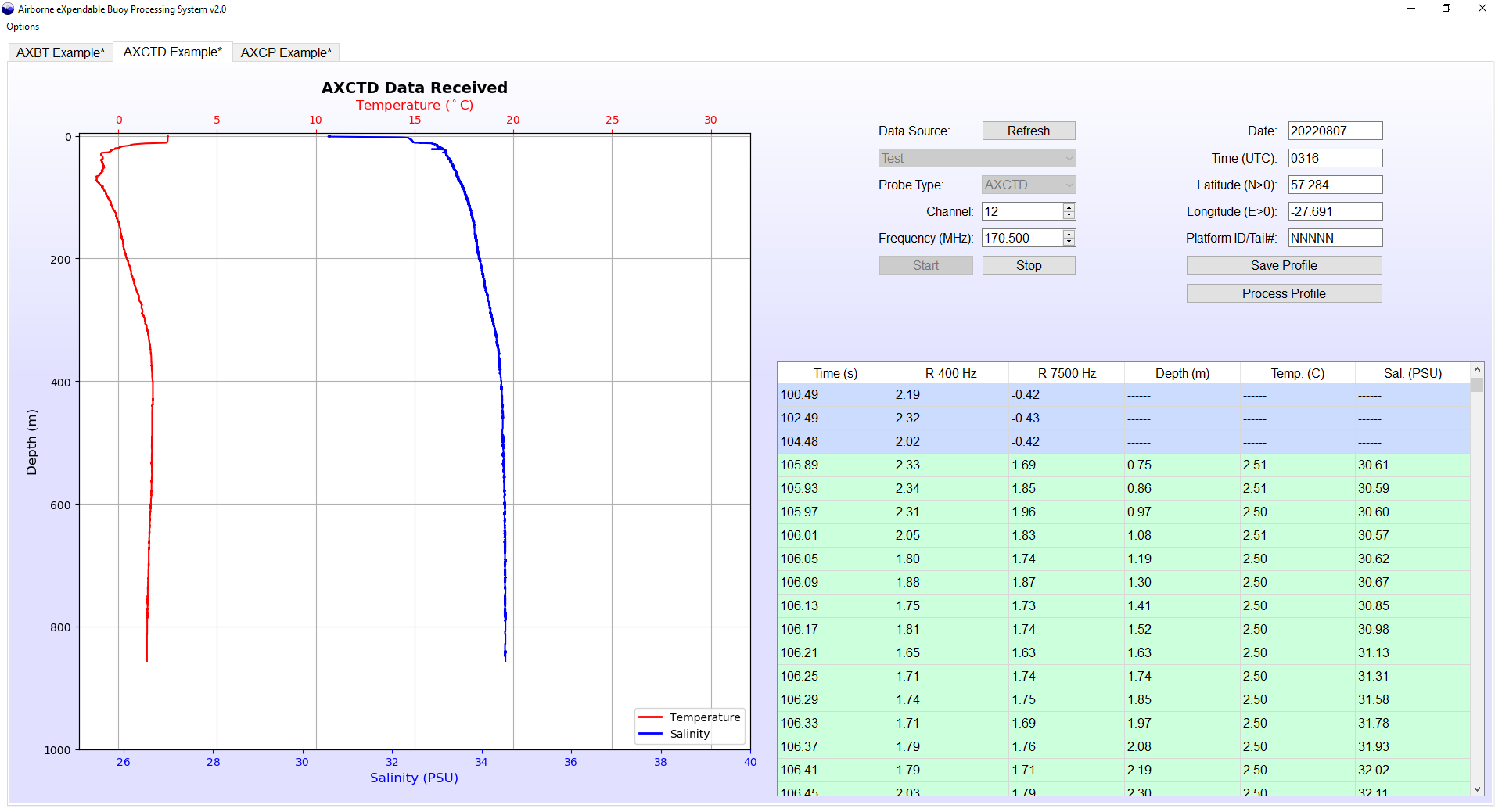
When processing an AXCTD, the table's columns are time (seconds), R400 (unitless), Δ R7500 (unitless), depth (meters), temperature (degrees Celsius), and salinity (PSU). The time, depth, and temperature fields are similar to the AXBT mode, with the addition of a salinity field. R400 and Δ R7500 are unitless signal-to-noise ratio metrics at 400 Hz and 7500 Hz, respectively. The former is used to identify when the AXCTD begins transmitting 400 Hz calibration tones, and the latter detects when the 7500 Hz tone indicating profile transmission has begun. These are both power levels provided as ratios to the power at a user-selected quiet frequency (default 3000 Hz, adjustable in settings), and must exceed user-selectable minimum thresholds (also adjustable in settings) for their respective tones to be identified. Prior to 400 Hz pulse detection and when bad datapoints are detected during profile collection, table entries appear gray. During the 400 Hz pulse and header calibration transmissions, table entries are blue. Table entries corresponding to valid datapoints will appear green.
When processing an AXCP, the table's columns are time (seconds), rotation rate mean and deviation (Hz; separated by a slash), depth (meters), temperature (degrees Celsius), and zonal and meridional (oriented in degrees True) currents (m/s). The time, depth, and temperature fields are similar to the AXBT and AXCTD modes, with the addition of two current fields. The rotation rate and rotation rate deviation are used to identify when an AXCP probe has "spun up" and begun descending through the water column (as it descends, it rotates at approximately 16 Hz). The rotation rate must be between 12 and 18 Hz for AXBPS to identify probe spinup, and spinup and spindown rotation rate deviation thresholds are adjustable in the DAS signal settings (discussed in the next section). Table entries before spinup or after spindown are gray, whereas entries containing valid profile data are displayed in green.
Settings
Data Acquisition System Settings
The Data Acquisition System settings are separated into two tabs: DAS General Settings and DAS Signal Thresholds. The DAS General Settings tab includes three sections: autopopulation options, file save formats, and miscellaneous settings. The autopopulation options (top left) control whether AXBPS automatically updates the recorded drop information (in the right column in the Data Acquisition System tab) whenever "Start" is selected for the first time in a tab. Autopopulation is not used when data is being reprocessed from a raw audio file (when "Audio" is the selected data source). Four file save formats are also selectable. Below these options are three additional user settings that control user prompts that appear when attempting to save the raw data and transition to a Profile Editor mode.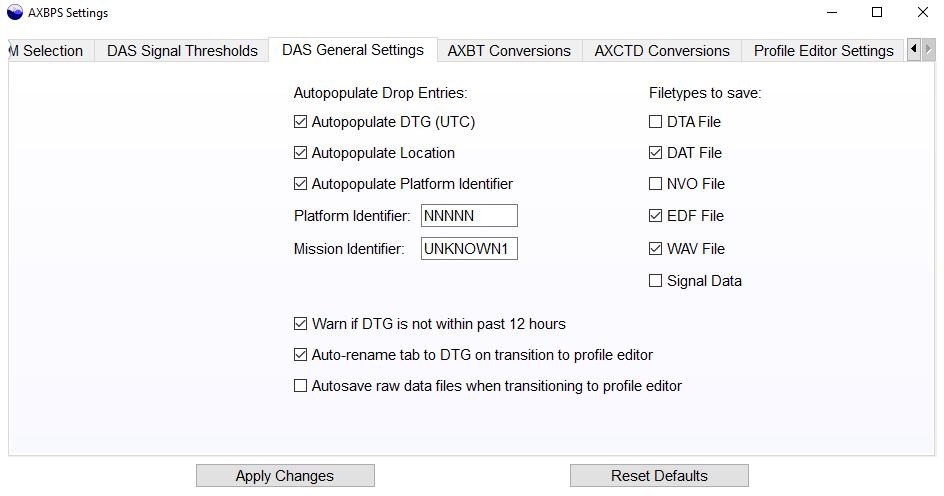
The DAS Signal Thresholds tab is divided into three sections by column for AXBT, AXCTD, and AXCP settings. The leftmost column of settings from the right control the windows and thresholds used to process AXBT data. The "FFT Window" is the length of each window of data (in seconds) used to determine peak frequency and corresponding temperature. Increasing this window increases the frequency and temperature resolution and reduces the effects of transient interference and noise, but also increases computational expense and slows the program, reducing the rate at which data can be processed and decreasing the raw profile's vertical resolution (this effect is compounded when processing multiple profiles simultaneously). The minimum signal level and signal ratio are thresholds used to distinguish valid AXBT data from noise (increasing the thresholds by moving the sliders to the right makes the Data Acquisition System more selective, reducing the amount of data considered valid). These minimum thresholds are applied to the values listed in the SP and RP (respectively) columns of the table. Finally, the trigger signal level and ratio are additional constraints applied to to the minimum signal level and ratio to identify the first datapoint transmitted from an AXBT and trigger the start of the temperature-depth profile. Because AXBT signals typically begin stronger and weaken with depth as the aircraft generally moves away from the buoy, using a higher constraint here can help to prevent weak VHF interference from erroneously triggering data collection prematurely.
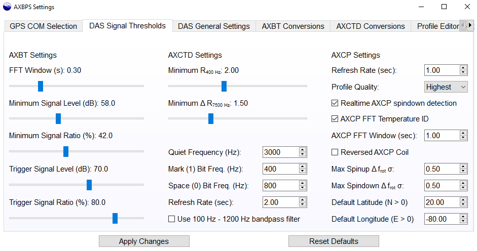
The middle column of settings pertain specifically to AXCTD decoding. The minimum R400 and Δ R7500 sliders allow users to set the minimum threshold for the respective signal-to-noise ratios at 400 Hz and 7500 Hz used to detect AXCTD calibration tone and profile transmission. Below those two sliders, the user can use the quiet frequency field to select a frequency somewhere between 1000 and 7000 Hz that should not contain any noise. The frequency shift key modulated data is transmitted at 400 and 800 Hz, and the profile tone at 7500 Hz, so the default of 3000 Hz is suitable unless known narrowband RF interference is expected in that range. The mark and space bit frequency selectors are used by the demodulation algorithm and should not be adjusted unless there are known discrepancies with the AXCTDs waveform that require compensation. The refresh rate defines the interval at which audio data are relayed to buffers to be demodulated into a bitstream and parsed into temperature and salinity information. Finally, selecting the bottom checkbox allows the user to apply a 100 Hz to 1200 Hz bandpass filter rather than the default (and recommended for most use cases) low pass 1200 Hz filter. The filter is applied to decouple the 7500 Hz profile transmission tone from the bitstream and simplify the demodulation process.
Finally, the rightmost column of settings applies specifically to AXCP decoding. AXCP refresh rate determines the length of PCM data chunks (in seconds) that are processed at a time. One second is recommended for a variety of reasons beyond the scope of this site. The AXCP quality affects subsampling intervals for the AXCP data, and due to its negligible effects on processing speed it is recommend to keep the highest quality selected. When enabled (recommended), realtime spindown detection automatically detects when the AXCP probe has stopped spinning (and either the probe's cable is severed or the probe has reached the ocean bottom) and terminates profile processing without user intervention. When enabled, AXCP temperature FFT ID uses an FFT (as in the AXBT processing algorithm) to determine the temperature baseline frequency. While slightly slower, the effect on processing speed is fairly small and the alternative method of zero-crossing frequency calculations is much more susceptible to interference, thus this setting is also recommended. The AXCP FFT window determines the window length for the FFT (in seconds), and is only used when the corresponding checkbox is selected. Selecting "Reversed AXCP coil" rotates the currents by 180° and should not be done unless you are aware that the launched AXCP falls in this category. The maximum spinup and spindown rotation rate deviations (Hz) are used to identify when the profile starts and stops spinning, respectively. It is recommended to keep both thresholds at 0.5 Hz, with the exception of particularly noisy AXCP profiles where probe spinup is not automatically identified. In that case, the current best practice is to reprocess the profile from audio with spinup and spindown thresholds of 1.0 and 2.0 Hz, respectively. Finally, the default latitude and longitude are the coordinates used to calculate Earth's magnetic field components and declination (for AXCP current calculations) if no coordinates are provided by the user. These settings will not autopopulate in the DAS latitude and longitude entry fields, and are not used for quality control and/or the profile editing system.
Conversion Equation Settings
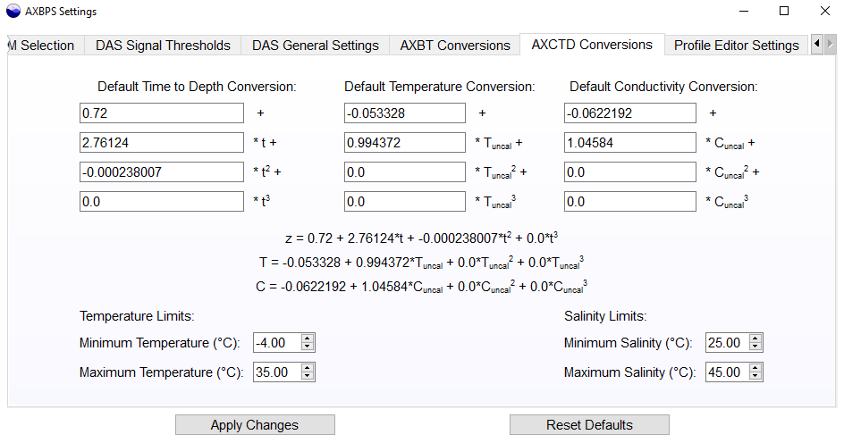
AXBPS includes the ability to use customized linear, quadratic, or cubic conversion equations for AXBTs in the AXBT Conversions tab. Two columns are provided: one for frequency-to-temperature and the other for time-to-depth conversions. To adjust the conversion equations being used, enter the coefficient for each term in its respective box. The equation at the top of the respective column should update to reflect the coefficients in the boxes. If non-numeric characters are entered, the equation will not update. The equations used by AXBPS will not be updated until ``Apply Changes" is selected. Additionally, if the contents of the input boxes do not match their respective equations (e.g. due to a non-numeric character as described above), the coefficients used by AXBPS are based on the equations at the top of each column, not the contents of the input boxes. Finally, at the bottom of the tab there are two additional inputs to select the valid frequency range. The default range of frequencies AXBPS accepts as valid AXBT signal is 1300 Hz to 2800 Hz, corresponding to approximately -3.9 °C to 37 °C. However, because AXBPS may be used in locations where only a subset of these temperatures are expected (e.g. an AXBT launched in the Southern Ocean during austral winter would most likely not observe 20 °C ocean temperatures), this input can be used to apply more precise constraints on the frequencies (and therefore temperatures) that AXBPS accepts. Similar to the AXBT options, AXBPS includes an AXCTD Conversions settings tab where users can specify the default temperature and conductivity calibration equations and the fall rate equation to calculate depth for AXCTDs. AXCTDs should transmit these fields with their header metadata prior to profile transmission, but should the AXCTD processing algorithm fail to identify and/or demodulate/parse the header data for a variety of reasons, the default equations will be used instead. Header metadata is saved in the sigdata.txt file and .edf file for each probe (if those file save options are enabled in the DAS settings) for users interested in that information. The AXCTD Conversions tab also includes min and max thresholds for valid temperature and salinity data. These thresholds, particularly the salinity threshold, are the most effective ways of distinguishing good profile data from random noise and interference that occasionally overcome the AXCTD's cyclic redundancy checks. Due to the complex nature of AXCP conversions (e.g. probe gain and phase angles, nonstandard temperature conversions) and lack of literature and competing conversion equations, an AXCP conversion settings tab is not provided.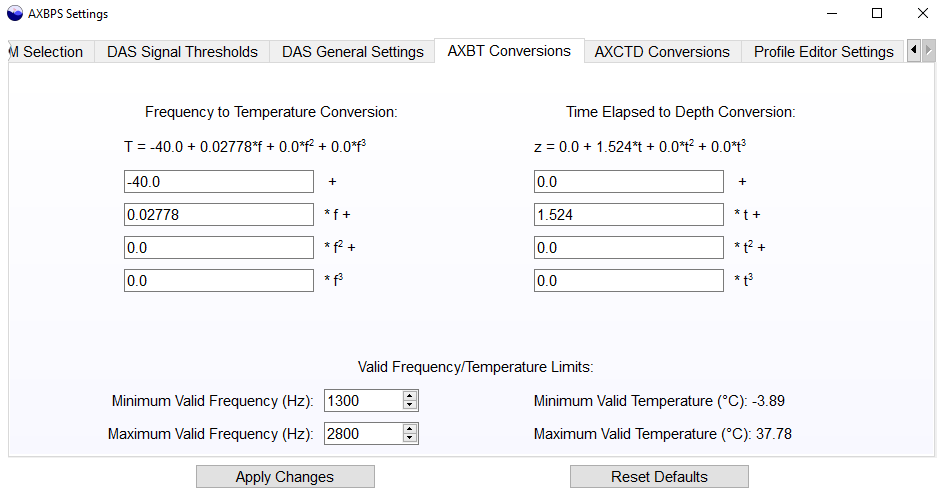
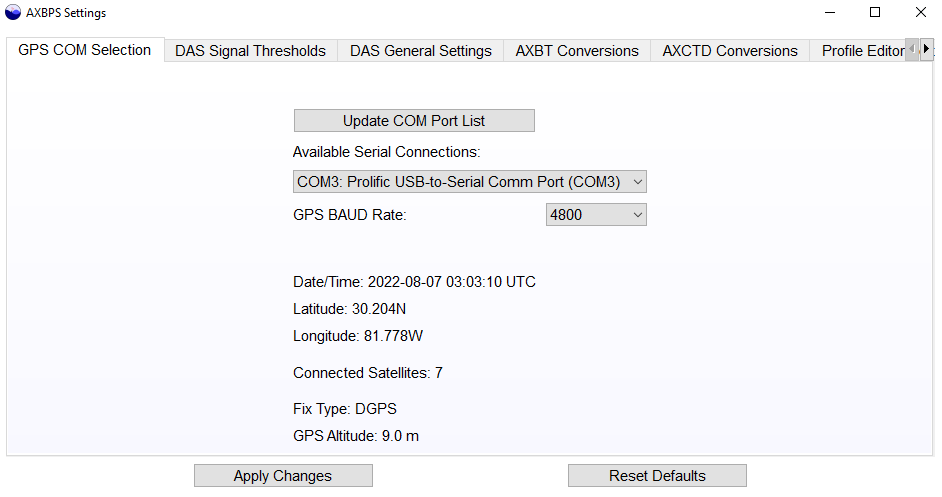
GPS Configuration Settings
The GPS settings tab allows the user to select a serial port for AXBPS to open and collect GPS data in order to autopopulate drop latitude and longitude when processing is started (more information on the GPS NMEA stream and RS-232 configuration is provided in the user manual). The dropdown menu lists all available RS-232 interfaces (it is worth reiterating that all available interfaces are listed, not just those that are transmitting valid GPS NMEA data streams). If multiple COM/serial ports are available, the correct port can be determined by first selecting a port and then selecting "Refresh GPS Info". If an active GPS receiver is connected to the selected port, this will populate the most recent GPS fix from that receiver. Otherwise, a warning message will appear stating that a GPS data stream could not be identified.